PROJECT DETAILS
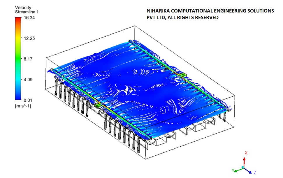
We carried out CFD analysis for the HVAC Jet Nozzle system proposed in the Wind turbine blade molding division at the LM wind power blade manufacturing plant in Bangalore. The blade manufacturing plant consists of four molding bays; for each bay, cold air will be supplied through 2 AHU units. Each AHU unit is connected to 40 Jet Nozzles. The main objective of this HVAC CFD analysis is to analyze airflow, air-impinging angle, and the flow regime. The flow regime plays a significant role from Health and safety perspective. We have explained our results to the Management of LM Wind power and recommended suggestions for Improvement.

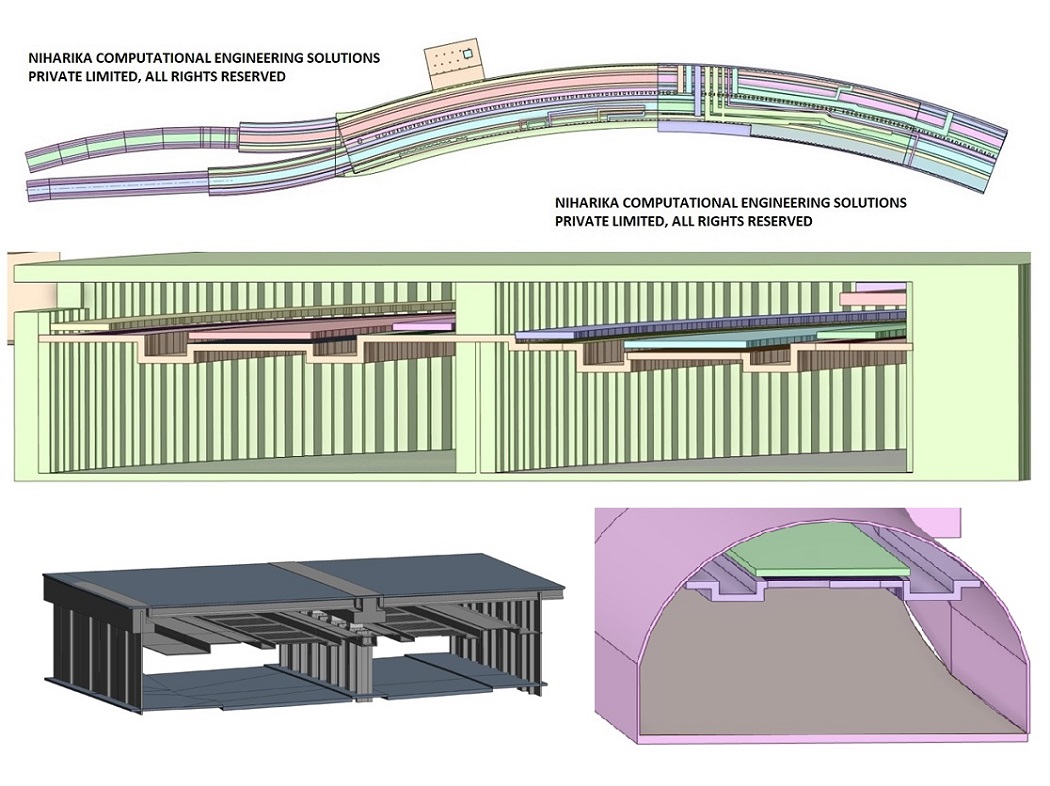
The 3D CAD model has been created to the required specifications for CFD analysis, utilizing the 2D Autocad drawings supplied by the Client. PTC Creo CAD software was employed for the generation of the 3D CAD model.
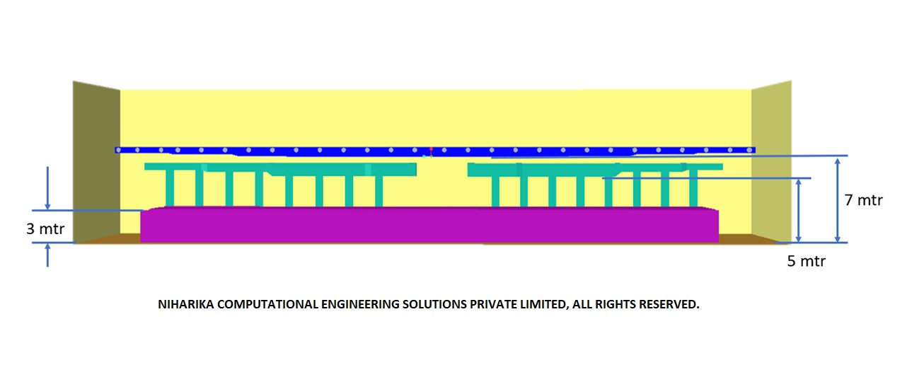
A CFD mesh has been developed for the simplified 3D CAD model mentioned earlier. This mesh consists of Poly Hex core elements, featuring suitable resolution in regions with high gradients. The overall cell count of the mesh is around 20 million, and it meets optimal quality standards, which contributed to achieving a well-converged solution.
CFD analysis is performed by adjusting the heights of the supply and return air ducts as per the Client's specifications. The flow is considered to be three-dimensional, steady-state, viscous, incompressible, and isothermal.
The flow field within the wind turbine molding bay is uniform, except for the area close to the nozzles. The highest velocity observed in the molding bay falls within the laminar flow regime, in accordance with the specified requirements.
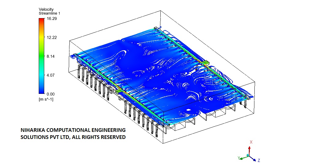
The flow field within the wind turbine molding bay is uniform, except for the area close to the nozzles. The highest velocity observed in the molding bay falls within the laminar flow regime, in accordance with the specified requirements.
We Got More
Go through All Our Case Studies
CFD analysis for underground transport tunnel:Al Shamiya Expansion Project,Makkah,Saudi Arabia
Underground tunnel infrastructure offers faster direct routes and excellent connectivity between communities. The tunnel needs a reliable ventilation system for continuous air provision to limit the concentration of air pollutants during normal tunnel operation and to transport smoke gases out of the tunnel during emergency smoke extraction. Our Computational Fluid Dynamics (CFD) simulation results have enabled our client to understand the flow development in the complete tunnel and gain confidence in the proposed Jet fans and various operating combinations of motorized dampers for smoke extraction in an emergency. Our precise CFD analysis results have enabled our client to make conscious engineering decisions to achieve better resource efficiency and safety compliance. Read MoreOptimization of hot and cold aisle rack/cabinet configuration in a data center using CFD analysis
The hot and cold aisles in the data center are part of an energy-efficient layout for server racks and other computing equipment. The goal of a hot/cold aisle configuration is to manage airflow in a way that conserves energy and lowers cooling costs. A containment system isolates hot and cold aisles from each other and prevents hot and cold air from mixing. Our client is executing a turnkey contract for a bank data center in Kuwait. We worked with our client from the beginning stage of the project and assisted them with our Computational Fluid Dynamics (CFD) analysis results. Our CFD analysis results have enabled our client to arrive at the best operating sequence of the cooling units. Read More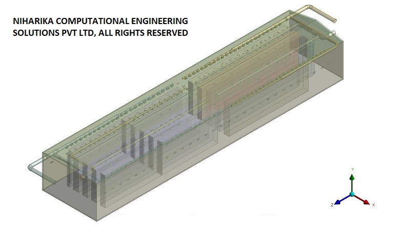
CFD analysis of Vaccine cold Storage warehouse HVAC System
A vaccine storage facility being constructed by Agility Pharma Logistics in Saudi Arabia requires an in-depth investigation of airflow dynamics and cooling processes within the warehouse through CFD analysis. To address this need, the contractor responsible for the cooling system has engaged Niharika Computational Engineering Solutions Pvt Ltd to perform a thorough CFD analysis and evaluate the air distribution in the planned ducting system. Read More
Turnkey solution to Wind Induced Noise in High Rise Building:Mahindra Windchimes Residential Tower01and02,Bangalore
Mahindra Windchimes is a high-rise residential complex situated on the outskirts of Bangalore, directly exposed to winds from the Bannerghatta reserved forest area. Residents have reported significant acoustic disturbances in the reception and common areas on the ground and first floors of Towers 01 and 02. To address this concern, Mahindra Life Space Developers Limited has engaged Niharika Computational Engineering Solutions Private Limited (NCES) for a comprehensive engineering project. Read More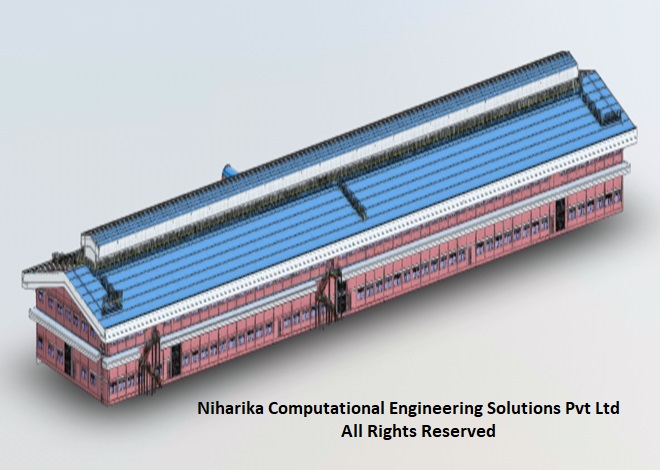
CFD analysis of Ventilation System in Shoe Manufacturing Factory-Taiwan Client
A construction engineering firm based in Taiwan has reached out to us for a CFD analysis to evaluate the effectiveness of the ventilation system in a shoe manufacturing facility currently under development. The project involves performing CFD analysis under various wind speed and ambient temperature scenarios in accordance with ISHRAE standards. Read More