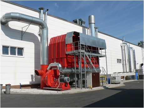
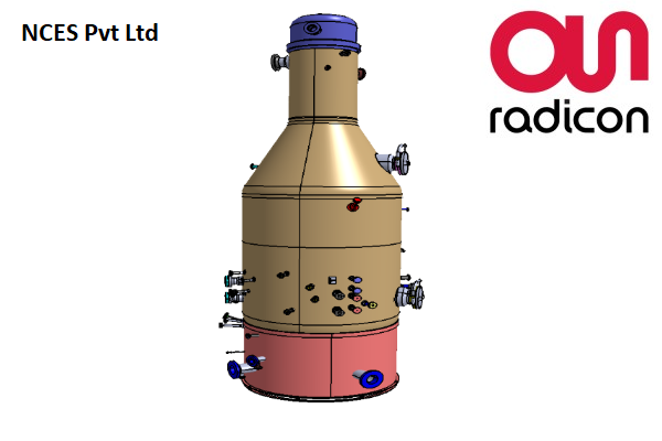
Regenerative Thermal Oxidizer (RTO)
Regenerative thermal oxidizers, commonly referred to as RTOs, are essential in the effective and economical removal of hazardous air pollutants (HAPs) and volatile organic compounds (VOCs) from industrial emissions. These thermal oxidizers are specialized combustion systems incorporated into the ventilation of industrial operations that produce potentially harmful pollutants. As exhaust gases pass through the oxidizer, it is heated to approximately 1500°F, facilitating the breakdown of HAPs and VOCs into benign substances such as carbon dioxide and water vapor, which can subsequently be released into the atmosphere. RTOs typically employ conventional metallic shell-and-tube heat exchanger systems, whereas regenerative thermal oxidizers utilize ceramic media beds that offer superior thermal efficiencies. In a dual-bed regenerative thermal oxidizer, the incoming process emissions are either drawn or forced through the initial ceramic bed by means of a high-pressure fan and pneumatic flow control valves. The contaminated stream exits the ceramic bed and enters the combustion chamber, where burners effectively decompose the harmful compounds with a destruction efficiency exceeding 99%. The resulting purified stream is then directed through a secondary ceramic bed, where it can transfer up to 97% of its heat value to the exchange medium. Regenerative thermal oxidizers capitalize on this recovered heat by periodically reversing the flow direction through pneumatic valves. The ceramic bed that has absorbed heat from the purified stream is subsequently employed to preheat the incoming emissions, while clean, cool air is released into the atmosphere.
Electrically Heated Regenerative Thermal Oxidizer (eRTO)
RTO equipment typically operates with burners that utilize gas or fuel to heat the oxidation chamber during the start-up phase, facilitating the oxidation of VOCs. In the case of flameless RTOs, the absence of a burner means there is no flame and consequently no NOX emissions produced. Instead, the oxidation chamber is heated by electrical resistances installed within it.
During the start-up process, these electric resistances function at full capacity to achieve the necessary temperature in the RTO oxidation chamber. Once operational, the electricity consumption will vary based on the VOC concentration at the inlet and its calorific value. If the concentration exceeds the auto-thermal threshold, the resistances will deactivate. Conversely, if the concentration falls below this threshold, the thyristors will adjust the power to the resistances to maintain the oxidation chamber at the required temperature, ensuring effective oxidation of VOCs.
Electrical RTO technology offers several benefits like Very High VOC elimination,High thermal efficiency, Integrated design with small dimensions and simple installation,Reduced maintenance and very high reliability, Less noise around the equipment due to the lack of a burner fan, Low operating costs, very minimal maintenance etc.
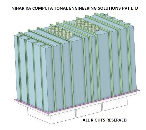
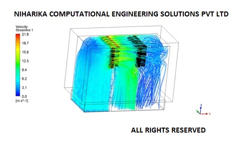
CFD analysis of Regenerative Thermal Oxidizer
Our client is a German company with a rich legacy spanning six decades in the field of industrial air pollution control and energy recovery systems. The client is currently working on a range of eRTO designs with varying capacities. Niharika Computational Engineering Solutions (NCES) has been assigned the task of performing Computational Fluid Dynamics (CFD) analysis and providing the design team with technical recommendations derived from the CFD findings.
The NCES team has successfully completed CFD analysis for approximately 12 different eRTO designs and has delivered all outputs well in advance of project deadlines, ensuring a high degree of accuracy in the CFD analysis.
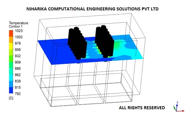
CFD analysis results
Precisely capturing the velocity and thermal boundary layer around approximately 2500 to 4000 closely arranged heater fins presented significant challenges related to mesh count and quality metrics.
The NCES team, with a legacy of over thirty years in CFD analysis, has adeptly addressed these practical challenges linked to the intricate eRTO CFD model and has performed CFD analysis with complete assurance.
Our accurate CFD analysis outcomes have empowered our client to make timely and well-informed technical decisions.
We Got More
Go through All Our Case Studies
Mechanical and Structural design of Disk baffle for Oligomerisation reactor
We executed this project for a SABIC Petrochemical plant located in Al Jubail, Saudi Arabia. The proposed disk baffle is expected to serve the function of separating the condensate in the Oligomerisation reactor. We developed the conceptual model of the disk baffle using our expertise in core mechanical design and optimized the design using Finite Element Analysis (FEA). We provided detailed fabrication drawings to the customer and supported them during Fabrication process. Read More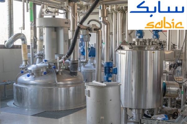
CFD analysis of Helical Agitator
Helical agitators are a type of mixing equipment consisting of ribs or blades arranged in the form of a helix. This design creates axial motion and vigorous fluid motion inside a vessel. It is often used to mix viscous materials. The helical agitator is commonly used for low Reynolds number industrial mixing. The helical design of these agitators generates high shear rates and ensures thorough mixing of materials with different densities and viscosities. Helical agitators are used in polymer industries and other industries that require the use of quite viscous materials. Read More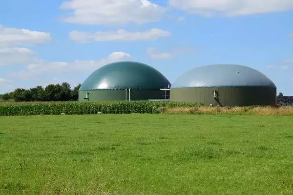
CFD analysis of anaerobic Bio digester-Multiphase flow CFD analysis
. Effective mixing within the digester promotes biological, chemical, and physical uniformity, preventing the creation of dead zones that hinder substrate conversion. Insufficient mixing can lead to reduced digester performance, while excessive mixing may disrupt the digestion process due to high shear forces. Therefore, it is essential to thoroughly understand and examine the optimal mixing techniques in anaerobic digesters. Read More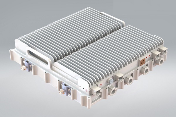
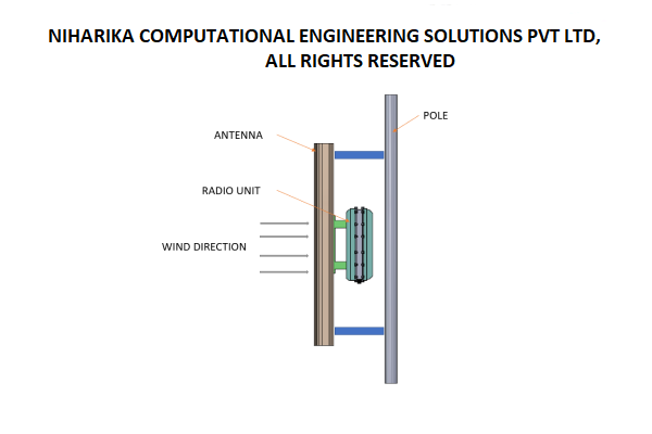
CFD analysis of Multi Band Remote Radio Unit
The advent of 5G technology has brought about unprecedented advancements in wireless communications, enabling faster speeds, lower latency, and increased capacity. These advancements are associated with higher power consumption and increased heat generation in the 5G Remote Radio units.Increasing data rates and network densification require radio units to process larger volumes of data, leading to higher power consumption and heat generation. Environmental factors such as ambient temperature, humidity, and exposure to direct sunlight also impact the thermal aspects of the radio units. Read More